Motivation

According to the listing the board was "Tested, working" and the seller even did a retest prior to sending which reported on "Retested, working". So all great... until it arrived.
Upon testing, I realized the inputs were not working properly. Buttons were mostly okay, but only the left direction was working, and the same afflicted the input 2. I thought that it could be some sort of non-standard JAMMA input mapping, and even replaced the EPROMs with the 2 player version of the game, but problem persisted.
Understanding the problem
Finally I decided to take a look at the schematics. On page 17 of a PDF manual I downloaded, I found the input section, which looked like this:

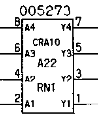
Okay, so it looks like all inputs go through a component labeled 005273, which are labeled RN1 to RN10. And guess what? it seems to be grouping together similar inputs for player 1, 2, 3 on each component, for example, RN3 has UP inputs for player 1, 2, 3 going through. Then, I inspected the board and...

Coming up with a solution
So I only need 2 but here lies the problem: 005273 is a Konami custom chip, and obviously cannot be bought easily. The solution is to rebuild it then, and for that, I searched the Internet for schematics but none were there to be found... I could find a few pictures of reproductions that already existed, but none had component values, etc. So I would have to do this on my own.

In comes your run-of-the-mill component tester that you can get anywhere from ebay to Amazon. These devices while not the most accurate, military grade, certified calibrated thing around, are very useful and versatile. So off I go to start testing.
From the pictures I found on the internet I could see that there were capacitors involved, so I decided to test every leg and see what it would produce. One thing I did first was to test each pin on an RN slot on the PCB to see if they would "beep" to ground or power. That's pin 9 (Vcc) and pin 10 (GND).
Measurements
So here was my testing method: Test every leg against Vcc, every leg against GND, and then each leg pair. Since JAMMA inputs are with negative logic, that is, 0v = on, 5v = off, there has to be pull-ups for each input, so most likely Vcc connections will be resistors, and the only reason to have GND on the component would be to use filter capacitors, so most likely these are the components connecting between the legs and ground.

On row two, each leg on even pins gave me also around 350 nF indicating a series capacitor with those pins, and similarly, 3.3KΩ on the odd pins indicating series resistor for them.
On row three (excuse my getting a bit lazy on the annotations) the even pins to Vcc gave 3.52KΩ, indidcating the path with the 220Ω and then 3.3KΩ resitors, similarly tests in between legs of the same type game me doubled values, which again indicates two components of the same type on the path between them. I did some other exotic measurements to confirm the results I was coming up with.
With all of that information, this is the schematic I came up with:

Prototyping the solution
To test, I figured I could cut some corners. For instance, all capacitors would go, and so the 220Ω resistor between input and output, which would basically just end up in a jumper for each pair with a pull-up resitor. I used 4.7KΩ because it was what I had in hand at the moment.
It's not elegant but it proved to work just fine
Doing it right
Well I obviously don't see that as a final solution, and at this point, I figured I was way deeply invested into this to just buy a replacement online. Time to design my own PCB.


With a black solder mask it fits right in.
I haven't manufactured these yet and I don't plan on selling these if I do. If and when I make them, I will post some pictures of the end result if there are some interest. I've also considered getting some dipping epoxy and coating it so that it looks even more genuine.
But why is this component like this?
Why the complexity and not simply a resistor array for the pull-ups? Well this is made as such to address noises that the input harnesses can pick up, especially when the wires are long. So each input goes through a RC filter and there's an additional power filter for the pull-ups. I obviously didn't know much about arcades so this all a journey of discovery for me. Glad you're coming along.
See you on the next post. 😁👍
Comments
Post a Comment